Observe lateral stability corrections, oscillations, and control authority on a secured platform.
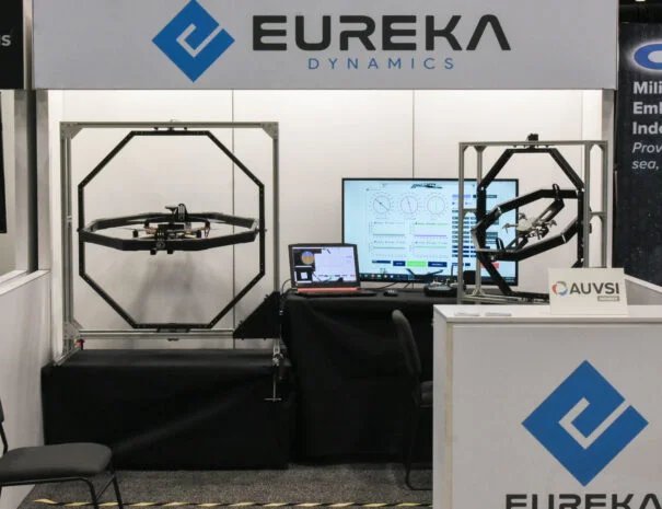
EUREKA DYNAMICS
Advanced Drone Testing Systems
The most precise, modular and scalable test platform for UAV R&D, manufacturing validation,and mission-critical drone operations.
What Is FFT-GYRO
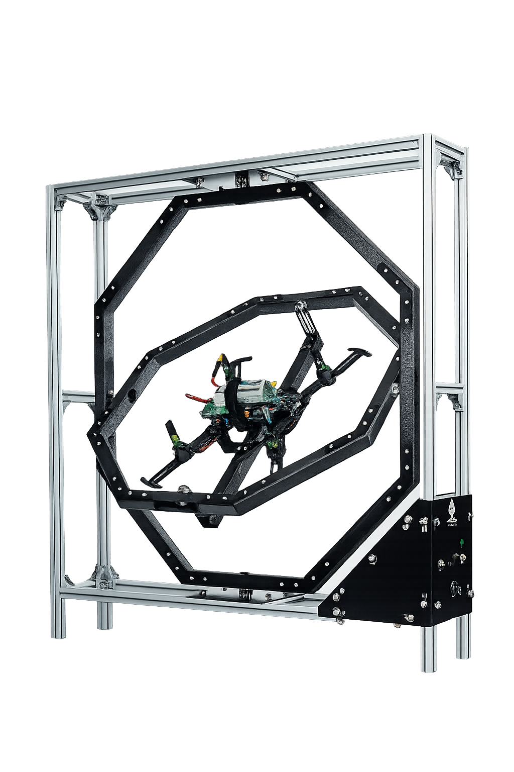
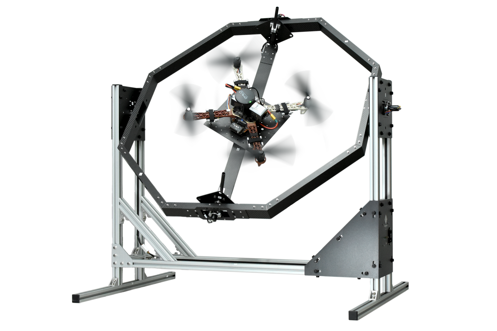
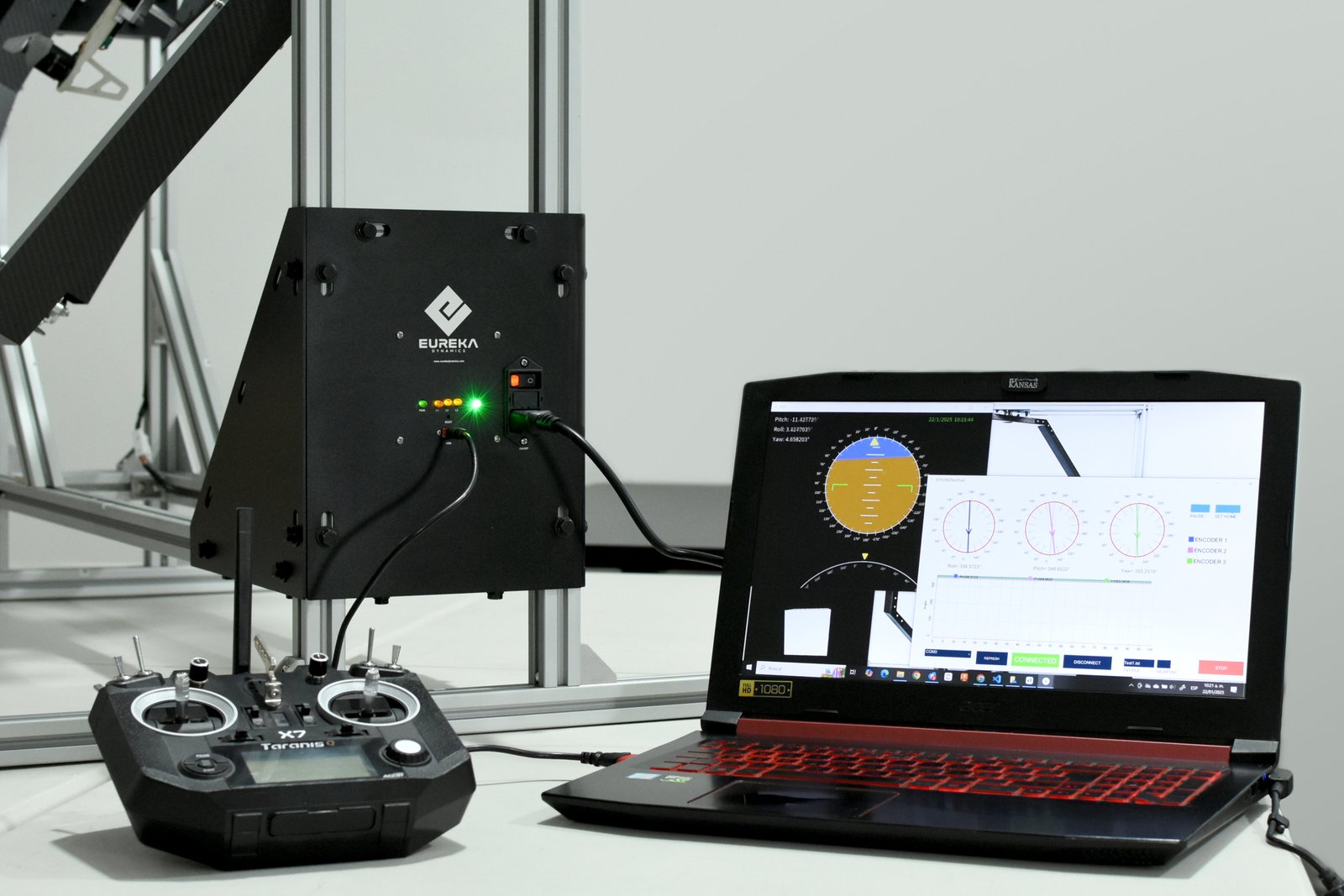
FFT-GYRO is a first-flight tester gyroscope that supports the drone at the center while allowing meaningful roll, pitch, and yaw motion inside a secure structure.
Its adjustable geometry helps align the drone center of rotation with the gyroscope, supports different multirotor sizes and types, and can be installed in open or closed spaces.
The FFT GYRO is a specialized gyroscope that can move freely in the roll, pitch, and yaw axis without any limitation, while supporting a drone in the center. Its safe structure allows the system to be installed in an open or closed space and interact with people in real time. With its adjustable height for different multi-rotors, the center of rotation of the drone can be aligned with the center of rotation of the gyroscope allowing the drone to rotate about it’s true center of rotation. It can hold different types and sizes of multi-rotors, from small racing drones to big industrial drones.
The FFT-GYRO is essentially useful for everyone that works with drones or UAVs. From beginner users that want to learn how to fly, to drone development companies that want to keep leading the market. It comes out as a solution for a wide variety of problems that are very common in this field. The FFT GYRO is not only a tool for research and development. It is the tool that makes easy to work with drones and helps to stay ahead of the game.
Roll, pitch, and yaw are organized so the aircraft can be observed under thrust without leaving the frame.
Observe lateral stability corrections, oscillations, and control authority on a secured platform.
Study thrust-vector response, balance changes, and the effect of center-of-mass placement.
Validate heading behavior, command response, and the way the aircraft rotates around its vertical axis.
SAFE VALIDATION
With a rig like this you could “fly” your drone anywhere without the risk of a collision.
Validate, calibrate and certify your drone designs before shipping.
Research and teach with the most advanced drone testing platform available.
Perform tests safely with your new accessories, devices or software.
Test third-party components and validate integration before deployment.
Practice maneuvers and refine skills safely without risk of crash damage.
Simulate Mission-Critical Environments for experimental UAVs.
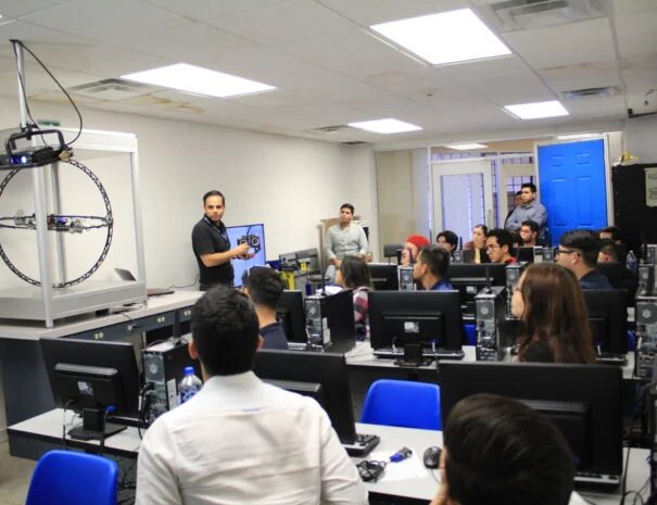
Bring real drones into the student's classroom and teach them the principles, uses and the operation of UAVs, in a completely safe environment.
Train new pilots in any indoor facility and give the opportunity to more experienced pilots to practice maneuvers without the need of going to an outdoor location.
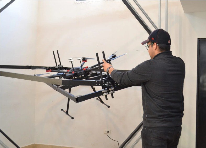
Bring this tool to the field to balance the weight distribution of the aircraft payload, tune the PID parameters and calibrate the on-board sensors before flight to avoid accidents.
Perform the On-board calibrations (IMU, gyroscopes and magnetometer) easily. Tune the PID parameters by trial and error without the stress of making a mistake.
Add a dynamic touch to your company and create an awesome experience for your customers by letting them "fly" your products, without putting them at risk.
Empower your R&D department to take that leap from investigation to experimentation and implementation in real-drones, performing projects easier and faster.
and more...
Different Gimbal Configurations
the system G3.5 keeps Roll → Pitch → Yaw and the system G4.0 moves Yaw first, which changes inertia, response feel, and the mounting approach around the drone.
Roll-first architecture with direct AHRS-aligned measurement logic and a hollow center for hardware clearance.
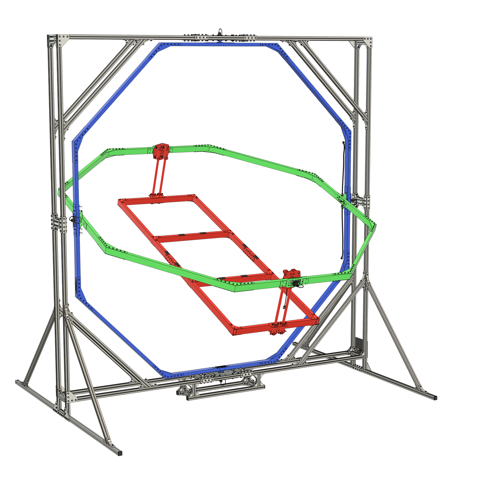
It favors conventional measurement logic and gives more open volume around the Drone center.
You want the published Roll → Pitch → Yaw stack and hardware clearance is a priority.
Same published axis result, different internal processing
G4.0 recalculates measurements internally, but the final published output remains Roll → Pitch → Yaw.
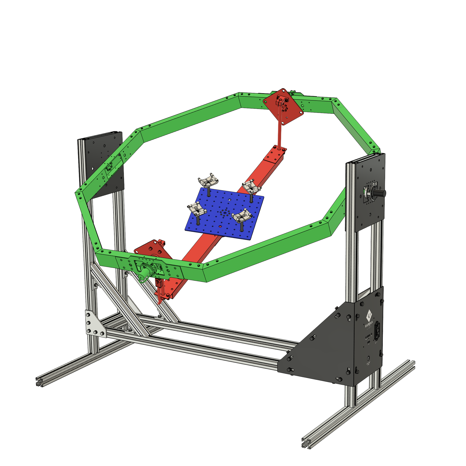
It keeps the expected published axis convention while adapting the internal measurement workflow.
Processed measurements may introduce a precision variation below 0.1%.
The full published table remains available here for deeper technical review.
| Feature / Version | G3.5 | G4.0 |
|---|---|---|
| Angle measurements | Follows the AHRS convention and takes direct measurements. | Does not follow AHRS directly and uses processed measurements. |
| Free channels for custom connection | Yes | No |
| Gimbal inertia | Fixed and stable inertia. | Reduced, but variable inertia. |
| Drone maneuverability | Yaw gimbal adds considerable inertia and affects maneuverability. | Better responsiveness for maneuver testing with near-real flight behavior. |
| Drone mount type | Hollow center with room for batteries, landing gear, payload, and other hardware. | Base plate mount that is easily interchangeable for customizations. |
Sizes / How To Choose
Start with the drone envelope. Rotor-to-rotor distance sets the shortlist, and outer diameter confirms the clearance the frame must preserve.
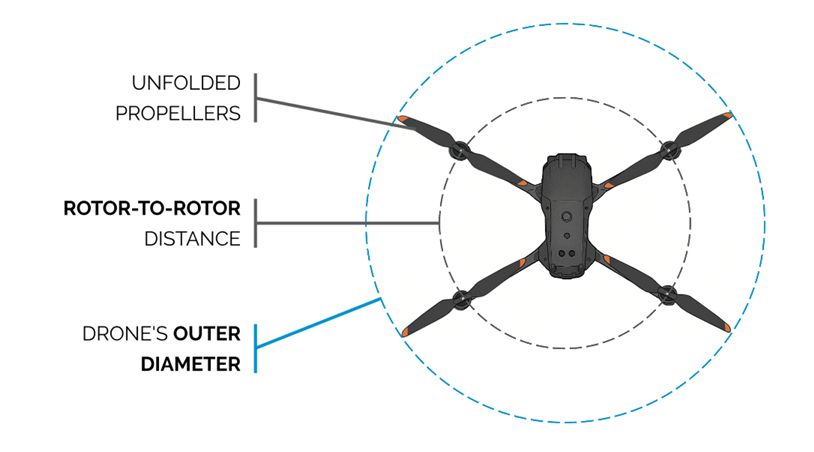
Use the main prop-center span to identify the correct FFT-GYRO family first.
Confirm the full aircraft envelope, including landing gear, payloads, and mounted hardware.
Avoid oversizing unless the total installed envelope truly requires a larger structure.
Use rotor-to-rotor distance and outer frame diameter together when you need the exact published range check.
| Spec / Size | 250 | 450 | 600 | 800 | 1000 | 1200 | 1500 | 2000 |
|---|---|---|---|---|---|---|---|---|
| Rotor-to-rotor distance (mm) | 100 - 250 | 250 - 450 | 450 - 600 | 600 - 800 | 800 - 1000 | 1000 - 1200 | 1200 - 1500 | 1500 - 2000 |
| Outer diameter (mm) | Up to 450 | Up to 750 | Up to 950 | Up to 1200 | Up to 1450 | Up to 1750 | Up to 2150 | Up to 2750 |
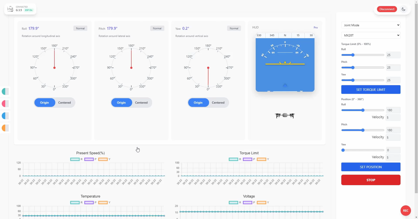
Software Ecosystem
The FFT-GYRO starts with the Standard version, which provides a robust mechanical gimbal for safe testing. If your workflow requires precise measurement, software integration, or motor-driven motion, the PRO version unlocks the system's advanced capabilities.
Add-Ons / Expandability
Motor kits turn FFT-GYRO into an active test system: size determines compatibility, and torque family tells you how much commanded force each axis can deliver.
Compatibility is published by platform size and shows where active torque modules can be added.
| Spec / Size | 250 | 450 | 600 | 800 | 1000 | 1200 | 1500 | 2000 |
|---|---|---|---|---|---|---|---|---|
| Motor kit compatibility | 1.4 and up | 3.0 and up | 4.1 and up | 7.3 and up | No | No | No | No |
Rated torque shows the continuous actuation level. Stall torque shows the peak holding limit of each kit family.
| Spec / Motor Kit | Motor Kit 1.4 | Motor Kit 3.0 | Motor Kit 4.1 | Motor Kit 7.3 | Motor Kit 10.6 |
|---|---|---|---|---|---|
| Rated torque (Nm) | 0.28 | 0.6 | 0.82 | 1.46 | 2.12 |
| Stall torque (Nm) | 1.4 | 3.0 | 4.1 | 7.3 | 10.6 |
Need extra technical details? Download full specs.
GET IN TOUCH
Book a live session with our engineering team to discuss your needs and get a custom solution.
Book NowReach out to our sales and engineering team for quotes, questions, or technical support.
info@eurekadynamics.comDOCUMENT LIBRARY